
ADI
图片可能具有代表性。
产品详情请参阅规格.
产品详情请参阅规格.
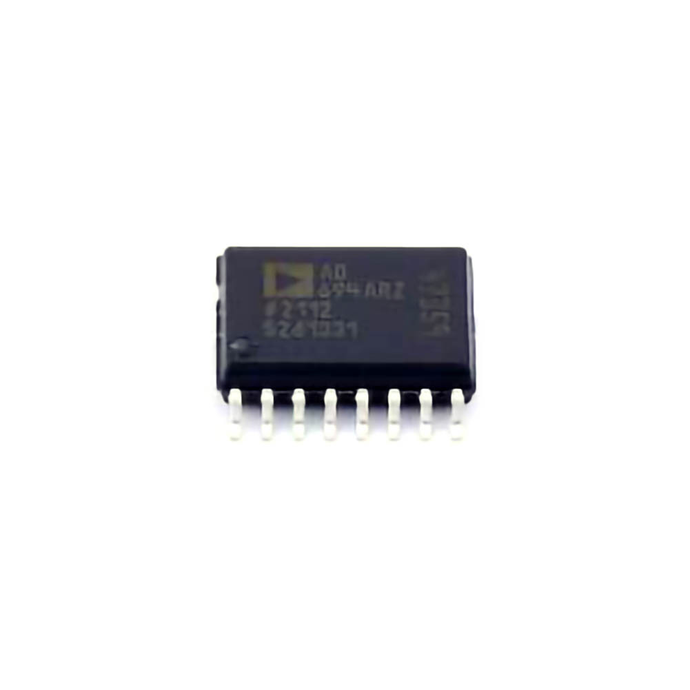
AD694ARZ
AD694ARZ
型号
AD694ARZ
类目
ADC/DAC/Data Conversion > Digital-to-analog conversion chip DAC
制造商/品牌
ADI
封装
SOIC-16-300mil
包装
Tube
包裹数量
47
简介
请求报价
请填写所有必填字段并点击“提交”,我们将在12小时内通过电子邮件与您联系。如果您有任何问题,请留言或发送电子邮件至 2762329346@qq.com,我们将尽快回复。
有货 90260 PCS
联系信息
more_pkgimg
more_schimg

more_3dimg
more_spec
AD694ARZ Product details
PRODUCT DESCRIPTION
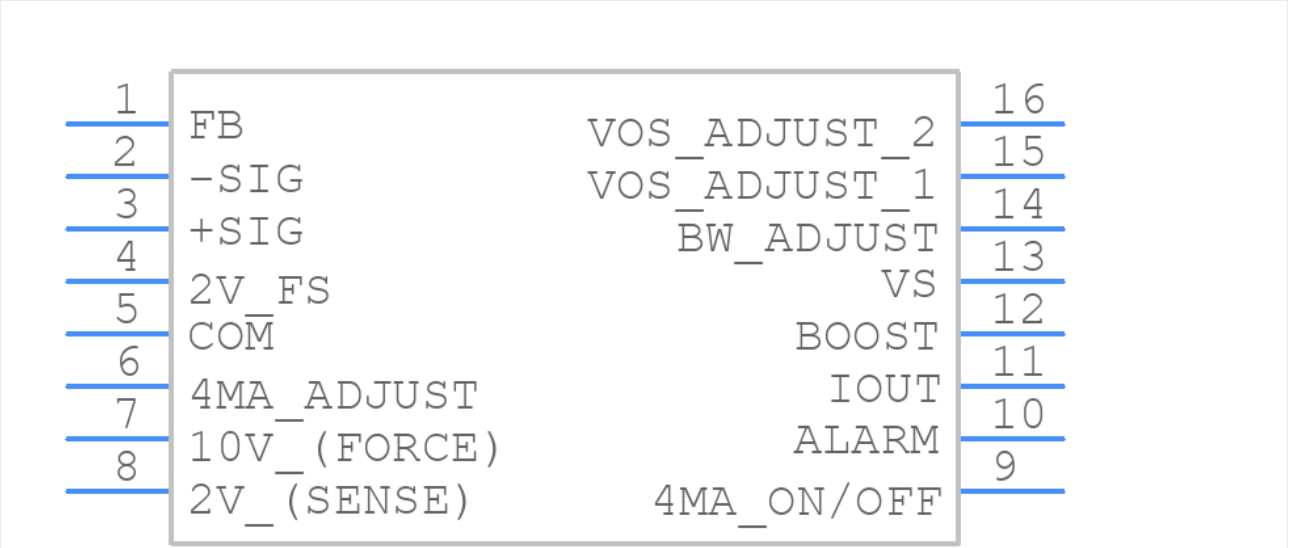
The AD694 is a monolithic current transmitter that accepts high level signal inputs to drive a standard 4–20 mA current loop for the control of valves, actuators, and other devices commonly used in process control. The input signal is buffered by an input amplifier that can be used to scale the input signal or buffer the output from a current mode DAC. Precalibrated in put spans of 0 V to 2 V and 0 V to 10 V are selected by simple pin strapping; other spans may be programmed with external resistors.
FEATURES
4–20 mA, 0–20 mA Output Ranges
Precalibrated Input Ranges: 0 V to 2 V, 0 V to 10 V
Precision Voltage Reference
Programmable to 2.000 V or 10.000 V
Single or Dual Supply Operation
Wide Power Supply Range: 4.5 V to 36 V
Wide Output Compliance
Input Buffer Amplifier
Open-Loop Alarm
Optional External Pass Transistor to Reduce Self-Heating Errors
0.002% Typ Nonlinearity
PRODUCT DESCRIPTION
The AD694 is a monolithic current transmitter that accepts high level signal inputs to drive a standard 4–20 mA current loop for the control of valves, actuators, and other devices commonly used in process control. The input signal is buffered by an input amplifier that can be used to scale the input signal or buffer the output from a current mode DAC. Precalibrated in put spans of 0 V to 2 V and 0 V to 10 V are selected by simple pin strapping; other spans may be programmed with external resistors.
FEATURES
4–20 mA, 0–20 mA Output Ranges
Precalibrated Input Ranges: 0 V to 2 V, 0 V to 10 V
Precision Voltage Reference
Programmable to 2.000 V or 10.000 V
Single or Dual Supply Operation
Wide Power Supply Range: 4.5 V to 36 V
Wide Output Compliance
Input Buffer Amplifier
Open-Loop Alarm
Optional External Pass Transistor to Reduce Self-Heating Errors
0.002% Typ Nonlinearity
more_desctext
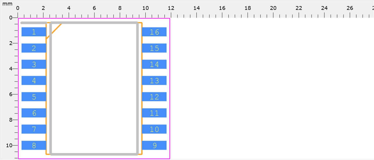
AD694ARZ, Current Loop Transmitter 16-Pin SOIC W
Pin Count--------16
Part Category--------Integrated Circuit
Package Category--------Small Outline Packages
Footprint Name--------Small Outline Packages - SOIC 300 MIL_2023_1
Pin Count--------16
Part Category--------Integrated Circuit
Package Category--------Small Outline Packages
Footprint Name--------Small Outline Packages - SOIC 300 MIL_2023_1
download_pdf
more_faq
AD694ARZ Frequently Asked Questions (FAQs)
What is the recommended PCB layout for optimal performance of the AD694ARZ?
A good PCB layout for the AD694ARZ involves keeping the input and output traces short and away from each other, using a solid ground plane, and placing decoupling capacitors close to the device. A 4-layer PCB with a dedicated ground plane is recommended.
How do I ensure the AD694ARZ is properly biased for optimal performance?
To ensure proper biasing, connect the VCC pin to a stable voltage source (e.g., 5V or 15V), and decouple it with a 0.1uF capacitor to ground. The VEE pin should be connected to a negative voltage source (e.g., -5V or -15V) or ground, depending on the application. The ISET pin should be connected to a resistor (e.g., 1kΩ) to set the output current.
What is the maximum output current of the AD694ARZ?
The maximum output current of the AD694ARZ is 20mA. However, it's recommended to limit the output current to 10mA to ensure reliable operation and minimize power dissipation.
How do I protect the AD694ARZ from overvoltage and ESD?
To protect the AD694ARZ from overvoltage and ESD, use voltage clamps (e.g., TVS diodes) on the input and output pins. Additionally, use ESD protection devices (e.g., ESD arrays) on the input and output lines. Follow proper PCB design and handling practices to minimize ESD exposure.
What is the recommended operating temperature range for the AD694ARZ?
The recommended operating temperature range for the AD694ARZ is -40°C to +85°C. However, the device can operate up to +125°C with reduced performance and reliability.
相关产品
关键词 AD694ARZ
AD694ARZ 电子元件
AD694ARZ 销售
AD694ARZ 供应商
AD694ARZ 分销商
AD694ARZ 数据表
AD694ARZ 图片
AD694ARZ 报价
AD694ARZ 提供
AD694ARZ 最低价格
AD694ARZ 搜索
AD694ARZ 购买
AD694ARZ 芯片
×
![]()